Safety Precautions and Important Safeguards
Always read all instructions carefully․ Avoid touching hot surfaces; use handles or knobs․ To prevent fire, electric shock, or injury, never immerse the appliance in water․ Keep children away and ensure the coffeemaker is placed on a stable, heat-resistant surface․ Unplug when not in use and follow all safety guidelines to avoid hazards․
1․1․ General Safety Guidelines
Read the manual thoroughly before use․ Avoid touching hot surfaces; use handles or knobs․ Keep children away and place the coffeemaker on a stable, heat-resistant surface․ Never submerge the appliance in water․ Unplug when not in use to ensure safety․ Follow all guidelines to prevent fire, electric shock, or injury․ Regularly inspect the power cord and plug for damage․ Use only original or recommended replacement parts to maintain safety standards․
1․2․ Initial Setup and Usage Warnings
Before first use, clean the coffeemaker thoroughly․ Wash the thermal carafe and brew basket in warm, soapy water, then rinse and dry․ Run two brewing cycles with water only to remove any dust or residue․ Avoid using abrasive cleaners to prevent damage․ Ensure all parts are properly assembled before brewing․ Follow the setup instructions carefully to ensure safe and proper operation of your Black+Decker coffee maker․
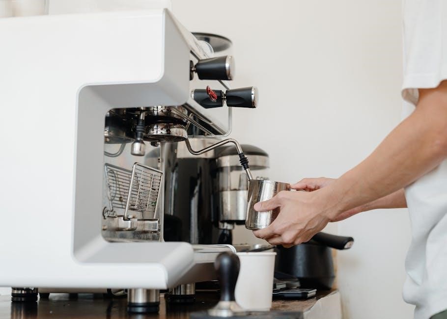
Understanding Your Coffee Maker Components
Your Black+Decker coffee maker includes a water reservoir, thermal carafe, brew basket, and control panel with buttons for settings․ These components work together to brew coffee efficiently and safely․
2․1․ Overview of the Machine Parts
Your Black+Decker coffee maker features a water reservoir, thermal carafe, washable brew basket, and a control panel with buttons for programming and operation․ Additional components include a carafe plate, power cord, and cord storage․ The machine is designed with a one-piece cover for easy access and cleaning․ These parts work together to ensure efficient brewing and convenient use, making your coffee-making experience straightforward and enjoyable․
2․2․ Key Features and Controls
Your Black+Decker coffee maker includes a 12-cup capacity, programmable digital clock, and delay brew feature for convenient scheduling․ The auto-off function ensures safety and energy efficiency․ Key controls include the BREW button for immediate brewing and the BREW LATER button for delayed starts․ Additional features like the carafe plate and cord storage enhance usability․ These components and controls are designed to simplify your coffee-making process, offering both convenience and customization options;
Brewing Coffee: Step-by-Step Instructions
Measure water, add to reservoir, insert filter, and add coffee grounds․ Select settings, press BREW, and wait for the cycle to complete․ Serve and enjoy!
3․1․ First-Time Cleaning and Preparation
Before first use, clean the coffeemaker thoroughly․ Wash the thermal carafe and brew basket in warm, soapy water, rinse, and dry․ Run two brewing cycles with fresh water only to remove any residue or dust․ Ensure all parts are dry before first use․ This preparation ensures optimal performance and clean-tasting coffee from the start․
3․2․ Brewing Process and Customization Options
Add fresh coffee grounds to the filter basket, then pour water into the reservoir․ Select brew strength and cup size․ Start brewing and customize settings like delay brew for convenience․ Adjust options to suit your taste preferences for a perfect cup every time․ Follow the manual for detailed guidance on customization to enhance your brewing experience․
Programming and Customization Features
Set the digital clock and customize brew strength․ Use the delay brew option to schedule brewing․ Adjust settings to suit your preferences for optimal results․
4․1․ Setting the Digital Clock
To set the digital clock, press the “HOUR” button until the desired hour appears․ Use the “MINUTE” button to adjust the minutes․ The clock will flash until confirmed․ Ensure the coffeemaker is plugged in for the clock to function․ Properly setting the clock is essential for scheduling brew times and maintaining accurate programming․ Follow these steps carefully for precise timekeeping and seamless operation․
4․2․ Delay Brew and Scheduling Options
Press the “BREW LATER” button to activate delay brewing․ Use the “HOUR” and “MINUTE” buttons to set your desired brew time․ The digital clock will flash until confirmed․ Once set, the coffeemaker will automatically start brewing at the programmed time․ This feature allows you to enjoy fresh coffee at your convenience, whether it’s for a morning routine or any time of day․ Ensure the clock is correctly set for accurate scheduling․

Cleaning and Maintenance Tips
Clean the coffeemaker regularly․ Wipe exterior with a damp cloth․ Wash carafe and brew basket in warm, soapy water․ Run brewing cycles with water only for deep cleaning․
5․1․ Daily and Deep Cleaning Instructions
Clean your Black+Decker coffee maker by wiping the exterior with a damp cloth; Daily, wash the thermal carafe and brew basket in warm, soapy water, then rinse and dry․ For deep cleaning, run two full brewing cycles with fresh water only, without coffee grounds, to remove any internal dust or residue․ Regular cleaning ensures optimal performance and prevents bacterial growth․
5․2․ Descaling and Troubleshooting Common Issues
Descaling your Black+Decker coffee maker regularly prevents mineral buildup․ Use a descaling solution or vinegar by running it through the brewing cycle without coffee grounds․ If the coffee maker doesn’t turn on, check power connections․ For issues with taste, ensure proper cleaning and water quality․ Refer to the troubleshooting guide for specific solutions to maintain performance and resolve common problems effectively․
Troubleshooting Common Problems
Identify common issues and refer to the troubleshooting guide for solutions․ Regular maintenance and proper usage help prevent operational problems․
6․1․ Coffee Maker Not Turning On
If the coffee maker won’t turn on, check the power source and ensure it’s properly plugged in․ Verify that the outlet is functioning․ Make sure all parts are correctly assembled and the carafe is securely placed․ If issues persist, consult the user manual or contact Black+Decker customer support for assistance․ Always follow troubleshooting steps to resolve the issue effectively․
6․2․ Issues with Coffee Taste or Brewing
If the coffee taste is off or brewing seems inconsistent, ensure the machine is clean and free of residue․ Run a brewing cycle with water only to rinse․ Check water quality and freshness, as impurities can affect flavor․ Verify the coffee-to-water ratio and grind size․ If issues persist, descale the machine to remove mineral buildup․ Adjust settings or consult the manual for further troubleshooting steps to achieve optimal brewing results․
Accessories and Replacement Parts
Explore compatible accessories like thermal carafes, washable brew baskets, and filters․ Find genuine replacement parts on the official Black+Decker website or authorized retailers․
7․1․ Compatible Accessories for Your Coffee Maker
Enhance your coffee-making experience with compatible Black+Decker accessories․ Thermal carafes keep coffee warm longer, while washable brew baskets offer convenience․ Water filters ensure optimal taste․ Explore additional accessories like replacement parts, cleaning solutions, and coffee grinder attachments․ Always check compatibility with your model to ensure proper functionality․ Visit the official Black+Decker website or authorized retailers for genuine products designed specifically for your coffee maker․
7․2․ Where to Find Replacement Parts
Replacement parts for your Black+Decker coffee maker can be found on the official Black+Decker website or through authorized retailers․ Visit the “Service & Support” section to search by model number․ Genuine parts ensure compatibility and safety․ You can also contact Black+Decker customer service for assistance or check trusted online marketplaces like Amazon․ Always verify authenticity to maintain your coffee maker’s performance and warranty coverage․
Warranty and Customer Support
Black+Decker coffee makers are backed by a limited warranty․ For inquiries, visit the official website or contact customer service for assistance with questions or concerns․
8․1․ Understanding Your Warranty Coverage
Your Black+Decker coffee maker is backed by a limited warranty covering defects in materials and workmanship for a specified period, typically two years․ The warranty is non-transferable and requires proof of purchase․ It does not cover damage from misuse, neglect, or unauthorized repairs․ For detailed terms, refer to your product manual or visit the official Black+Decker website․ Contact customer service for warranty-related inquiries or claims․
8․2; Contacting Black+Decker Customer Service
For assistance, contact Black+Decker customer service via phone, online chat, or email through their official website․ Visit the support section for FAQs, troubleshooting, and warranty inquiries․ Representatives are available to address concerns, provide repair information, or guide you through product registration․ Ensure to have your product model and serial number ready for efficient support․ You can also find contact details in your product manual or on the Black+Decker website․
Additional Resources and Manuals
Visit the official Black+Decker website for downloadable manuals, troubleshooting guides, and FAQ sections․ Additional resources include user guides, repair tips, and warranty information for your coffee maker․
9․1․ Downloading the Full User Manual
To access the full user manual for your Black+Decker coffee maker, visit the official Black+Decker website․ Navigate to the support section, select your specific coffee maker model, and download the PDF manual․ This comprehensive guide includes detailed instructions for setup, operation, maintenance, and troubleshooting․ It also covers safety precautions, warranty information, and programmable features to ensure optimal performance and longevity of your coffee maker․
9․2․ Online Support and FAQ Sections
Visit the Black+Decker website for extensive online support, including a dedicated FAQ section․ Find answers to common questions about your coffee maker’s operation, troubleshooting, and maintenance․ The FAQ section addresses topics like brewing issues, cleaning, and programmable features․ Additionally, interactive guides and customer support contact information are available to assist with any queries, ensuring a seamless experience with your coffee maker․