Kelley Dock Leveler Owners Manual: A Comprehensive Guide
This manual provides essential guidance for safe and efficient operation of your Kelley Dock Leveler, covering features like 360° coverage, 1080p video, and advanced AF systems.

Kelley Dock Levelers represent a commitment to safety and efficiency in loading dock operations. Designed for seamless integration with various dock configurations, these levelers facilitate the smooth transfer of goods between vehicles and facilities. Like modern cameras offering features such as 360° panoramic views and high-definition recording, Kelley Dock Levelers provide a clear and reliable connection point.
This manual serves as a comprehensive resource for owners, operators, and maintenance personnel. It details the leveler’s components, operational procedures, safety guidelines, and troubleshooting steps. Understanding the principles behind the leveler’s functionality – similar to grasping the capabilities of a 24.2MP CMOS sensor or a 64MP vlogging camera – is crucial for maximizing its performance and lifespan. Proper use and maintenance, as outlined herein, will ensure a safe working environment and minimize downtime, mirroring the importance of regular care for photographic equipment.
Understanding Dock Leveler Safety
Prioritizing safety is paramount when operating a Kelley Dock Leveler. Like ensuring clear footage with a security camera’s 1080p resolution, a safe dock environment requires vigilance and adherence to established protocols. This section outlines critical safety considerations to prevent accidents and injuries.
Always inspect the leveler before each use, verifying proper functionality of the safety edge, emergency stop, and hydraulic systems. Never exceed the leveler’s rated capacity, and ensure the dock area is clear of obstructions. Personnel should be thoroughly trained on operational procedures and emergency response. Just as a camera’s Night Sight feature enhances visibility in low light, understanding potential hazards is vital. Regular safety inspections, akin to checking a camera’s settings, are essential. Failure to follow these guidelines could result in serious consequences, emphasizing the need for consistent safety awareness.
Key Components of a Kelley Dock Leveler
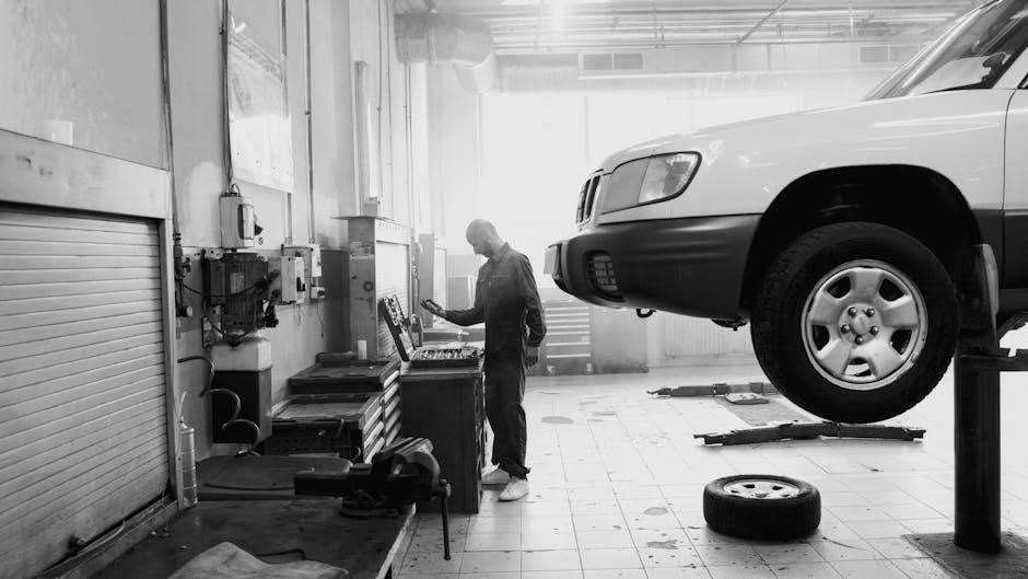
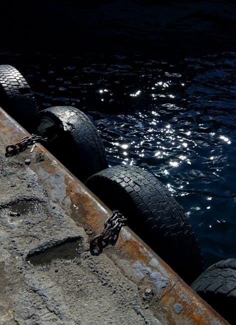
A Kelley Dock Leveler comprises several integral components working in unison to facilitate safe and efficient loading/unloading. Similar to a camera’s sensor capturing images, each part plays a crucial role. The primary elements include the dock plate – the actual surface bridging the gap – and the lip extension, which adjusts to accommodate varying truck bed heights.
The hydraulic system provides the power for raising and lowering, while the control panel allows for operator control. A critical safety feature is the safety edge, designed to stop the leveler’s descent upon impact. Like the panoramic view of an Ezviz H6c Pro camera, understanding each component’s function is key. Additional components may include side rails, leg assemblies, and a maintenance strut. Regular inspection of these parts, much like checking a camera’s zoom capabilities, ensures optimal performance and longevity.

Operation and Maintenance
Proper operation and consistent maintenance, like capturing clear footage with a 1080p camera, are vital for maximizing the lifespan and safety of your Kelley Dock Leveler.
Normal Operating Procedures
Prior to operation, visually inspect the dock leveler for any obstructions or damage, ensuring a safe working environment, much like checking camera lenses for clarity. Confirm the dock door is fully open and the truck is properly positioned and secured with wheel chocks. Initiate the raise/lower sequence using the control panel, observing the leveler’s movement for smooth operation – similar to the pan and tilt functions of a security camera.
As the leveler ascends, verify the safety edge engages correctly with the truck bed. Once contact is made, the leveler should automatically transition to a stable, level position. During loading/unloading, maintain constant visual awareness of the dock leveler and surrounding area. Avoid exceeding the leveler’s rated capacity. Upon completion, activate the return-to-rest sequence, ensuring the leveler fully retracts and locks into its stored position. Regular adherence to these procedures, akin to utilizing features like Night Sight on a Pixel Camera, will contribute to long-term reliability and prevent potential incidents.

Emergency Stop Functionality
The Kelley Dock Leveler is equipped with multiple Emergency Stop (E-Stop) buttons strategically located for immediate access – functioning as a critical safety feature, much like the quick access controls on a modern camera. These buttons, typically red and prominently displayed on the control panel and potentially on the dock leveler itself, instantly halt all movement.
In the event of an unexpected event, such as personnel entering the hazard zone during operation or a mechanical malfunction, immediately depress the nearest E-Stop button. This will cut power to the leveler’s hydraulic system, preventing further movement. To resume operation, the E-Stop button must be manually reset – often requiring a twist to release – before the leveler can be reactivated. Regularly test the E-Stop functionality to ensure responsiveness, similar to checking the automatic tracking on an Ezviz camera. Following an E-Stop event, a thorough inspection should be conducted to identify and address the cause before resuming normal operations.
Routine Maintenance Schedule
To ensure optimal performance and longevity of your Kelley Dock Leveler, adhere to the following routine maintenance schedule – mirroring the care required for high-performance cameras like the Sony Alpha 7 IV.
Daily: Visually inspect the entire leveler for any signs of damage, obstructions, or hydraulic leaks. Confirm the safety edge is functioning correctly. Weekly: Check and tighten all bolts and fasteners. Inspect the lip extension for wear and tear. Monthly: Thoroughly clean the leveler surface, removing debris and buildup. Examine the hydraulic hoses for cracks or abrasions. Semi-Annually: Perform a complete hydraulic system check, including fluid level and condition. Lubricate all moving parts as detailed in the Lubrication Guidelines. Annually: Schedule a professional inspection by a qualified technician – similar to a camera sensor cleaning – to assess overall condition and identify potential issues before they escalate.
Lubrication Guidelines
Proper lubrication is crucial for smooth operation and preventing premature wear of your Kelley Dock Leveler – much like maintaining a camera’s intricate mechanisms for optimal image quality. Use a high-quality, heavy-duty lithium-based grease specifically designed for industrial applications.
Grease Points: Regularly lubricate the hinge points of the lip extension, the pivot points of the leveler plate, and any other moving components identified in the Key Components section. Apply grease using a grease gun until it appears at the seals. Frequency: Lubricate these points every three months, or more frequently in high-use environments. Hydraulic Cylinders: Do not grease the hydraulic cylinders. They are sealed units. Avoid Contamination: Keep lubricants clean and free from dirt and debris. Inspect seals regularly for damage and replace as needed. Consistent lubrication, akin to careful camera handling, extends the life of your equipment.
Hydraulic System Checks
Regular inspection of the hydraulic system is vital for reliable dock leveler performance, similar to ensuring a camera’s internal systems function flawlessly for clear footage. Begin by checking the hydraulic fluid reservoir level. Maintain fluid between the “min” and “max” markings. Inspect hoses and fittings for leaks, cracks, or damage – address any issues immediately.
Pressure Test: Periodically perform a pressure test to verify the system is operating within the manufacturer’s specifications. Cylinder Inspection: Examine hydraulic cylinders for signs of leakage or damage to the seals. Air Bleeding: If the leveler operates slowly or erratically, air may be present in the system; consult the troubleshooting section for air bleeding procedures. Like a camera’s sensor, a healthy hydraulic system is essential for optimal function.
Troubleshooting Common Issues
This section details solutions for typical problems, ensuring swift resolution, much like diagnosing camera issues for optimal picture quality and performance.
Leveler Won’t Raise or Lower
If the dock leveler fails to respond to control commands, begin with a thorough visual inspection of the hydraulic hoses and connections. Look for any obvious signs of damage, leaks, or disconnections – similar to checking camera cables for proper function.
Next, verify the emergency stop button is not engaged; a pressed button will override all normal operations. Confirm the power supply to the control panel is active and that all safety edges are functioning correctly. A faulty safety edge can prevent operation as a protective measure.
Check the hydraulic fluid level in the reservoir. Low fluid levels can significantly reduce system pressure, hindering movement. If the fluid is low, replenish it with the manufacturer-recommended type. Consider the possibility of a blown fuse or tripped circuit breaker in the control panel, and reset or replace as needed. If issues persist, professional service is recommended.
Hydraulic Fluid Leaks
Hydraulic fluid leaks represent a serious safety hazard and can compromise the leveler’s functionality. Immediately address any detected leaks to prevent accidents and maintain optimal performance, much like ensuring clear footage from a security camera.
Begin by identifying the source of the leak. Carefully inspect all hydraulic hoses, fittings, cylinders, and the pump for visible fluid accumulation. Tighten any loose connections, but avoid over-tightening, which could cause damage. If a hose is cracked or damaged, it must be replaced immediately.
Clean up any spilled fluid promptly to prevent slipping hazards. Monitor the fluid level in the reservoir and replenish as needed with the correct type of hydraulic fluid. Persistent leaks may indicate internal seal failure within a cylinder or pump, requiring professional repair or component replacement. Regular inspection, similar to checking camera settings, is crucial.
Dock Leveler is Unstable
An unstable dock leveler poses a significant risk of accidents, potentially leading to product damage or, more seriously, personnel injury. Addressing instability is paramount, much like ensuring a clear, stable image from a security camera or a steady shot with a vlogging camera.
First, verify the dock leveler is correctly positioned and engaged with the truck bed. Check that the lip extension is fully supported and not overextended. Inspect the safety legs for proper deployment and contact with the truck’s rear impact guard. Ensure the dock itself is level and free from obstructions.
If instability persists, immediately stop all loading/unloading operations. Examine the leveler’s hinges and pivot points for wear or damage. A malfunctioning hydraulic system can also contribute to instability; refer to the ‘Hydraulic System Checks’ section. Do not attempt to operate an unstable leveler – contact a qualified technician for inspection and repair.
Control Panel Malfunctions
If the control panel exhibits erratic behavior, fails to respond, or displays error messages, immediately cease operation of the dock leveler. Similar to troubleshooting a camera app that’s frozen or a security camera with a distorted feed, systematic diagnosis is crucial.
Begin by checking the power supply to the control panel. Verify all connections are secure. Inspect the emergency stop button to ensure it isn’t inadvertently engaged. If the panel has a display screen, note any error codes and consult the troubleshooting section of this manual or contact Kelley’s technical support.
Do not attempt to bypass or repair the control panel yourself unless you are a qualified technician. Tampering with the electrical components can create a safety hazard. Consider the panel’s responsiveness akin to a camera’s autofocus – if it’s failing, professional attention is needed. Document the malfunction details for accurate repair.
Safety Edge Issues
The safety edge is a critical component designed to prevent injuries by stopping the leveler’s descent upon contact with an object. Like a camera’s image stabilization preventing blurry photos, the safety edge ensures operational security. If the safety edge fails to activate or the leveler continues to descend with pressure applied, immediately stop all operations.
Inspect the safety edge for physical damage, such as cuts, tears, or debris. Ensure the wiring connecting the safety edge to the control panel is intact and securely fastened. A loose connection can mimic a camera’s poor Wi-Fi signal, causing intermittent issues.
Test the safety edge functionality regularly using a soft object to simulate contact. If the edge doesn’t respond, or responds inconsistently, contact a qualified technician for repair or replacement. Never attempt to override or disable the safety edge system – it’s a vital safety feature.
Advanced Features & Adjustments
Explore fine-tuning options like lip extension and working range settings, mirroring a camera’s focus and zoom adjustments for optimal performance and tailored operation.
Adjusting the Lip Extension
The lip extension of your Kelley Dock Leveler is crucial for bridging the gap between the dock and the trailer, ensuring a secure and stable connection during loading and unloading operations. Proper adjustment minimizes stress on both the dock and the vehicle, preventing potential damage and enhancing safety.
To adjust the lip extension, locate the designated control mechanism – typically a lever or button – on the control panel. Consult the diagrams in this manual for precise location. Slowly operate the control, observing the lip’s extension. Ensure the lip fully contacts the trailer bed without excessive force.
Important Considerations: Avoid overextending the lip, as this can create a tripping hazard and potentially damage the leveler. Regularly inspect the lip for wear and tear, and adjust as needed to maintain optimal performance. Like a camera’s zoom, precise adjustment is key. Remember to always follow safety protocols during adjustment and operation, prioritizing a secure and efficient loading process.
Setting the Working Range
Establishing the correct working range for your Kelley Dock Leveler is paramount for operational safety and efficiency. This range defines the leveler’s maximum upward and downward travel, accommodating varying trailer heights. Incorrect settings can lead to instability, damage to equipment, or even accidents – much like a camera’s focus needing adjustment.
The working range is typically adjusted via limit switches located within the leveler’s control box. Accessing these switches requires qualified personnel and adherence to lockout/tagout procedures. Carefully adjust the switches to correspond with the typical height variations of trailers servicing your dock.
Crucial Notes: Always test the working range after adjustment, ensuring the leveler smoothly transitions through its entire range of motion. Regularly re-evaluate the settings if trailer heights change. Proper range setting, combined with features like two-way audio monitoring, contributes to a safer and more productive loading environment.
Understanding the Dock Seal Interface
The interface between your Kelley Dock Leveler and the dock seal is critical for maintaining a secure and energy-efficient loading environment. A proper seal minimizes gaps, preventing heat loss, protecting against weather elements, and enhancing overall security – similar to a camera’s lens protecting its sensor.
Kelley Dock Levelers are designed to work in conjunction with various dock seal types. Ensure compatibility between the leveler’s lip configuration and the seal’s mounting style. Proper alignment is key; the leveler’s lip should make firm, consistent contact with the seal when in the loaded position.
Important Considerations: Regularly inspect the dock seal for wear and tear, replacing damaged sections promptly. Verify that the seal isn’t obstructing the leveler’s movement. A well-maintained dock seal interface, alongside features like panoramic views and motion detection, contributes to a safer and more controlled loading process.
Maintenance of the Dock Leveler’s Surface
Maintaining the surface of your Kelley Dock Leveler is crucial for ensuring safe and reliable operation, much like keeping a camera lens clean for optimal image quality. Regular cleaning prevents buildup of debris, grime, and potential contaminants that could affect traction and smooth movement.
Use a mild detergent and water solution for routine cleaning. Avoid abrasive cleaners or solvents that could damage the surface finish. Inspect the surface frequently for dents, cracks, or corrosion. Promptly address any damage to prevent further deterioration and maintain structural integrity.
Consider applying a protective coating designed for industrial surfaces to enhance durability and resistance to wear. Similar to a camera’s protective housing, this safeguards against environmental factors. Regularly check and tighten any surface-mounted hardware. A well-maintained surface contributes to a safer and more efficient loading dock environment, mirroring the clarity of a 1080p video feed.
Safety and Compliance
Adhering to OSHA standards and conducting regular inspections are vital, ensuring your Kelley Dock Leveler operates safely, like a secure home security camera system.
OSHA Compliance Standards
Kelley Dock Levelers must adhere to stringent Occupational Safety and Health Administration (OSHA) regulations to ensure a safe loading and unloading environment. These standards, much like those governing security camera placement for complete coverage, prioritize worker protection. Key requirements include maintaining functional safety edges – similar to the motion detection on a modern surveillance camera – and ensuring proper communication between the leveler and the loading dock.
Regular inspections, documented meticulously, are crucial for demonstrating compliance. The control panel, akin to the settings on a high-definition camera, must be fully operational, and emergency stop functionality must be tested frequently. Proper signage indicating safe operating procedures is also essential. Failing to meet these standards can result in significant penalties and, more importantly, put personnel at risk. Like a reliable camera providing clear footage, a compliant dock leveler provides a secure workspace.
Regular Safety Inspections
Consistent and thorough safety inspections are paramount for maintaining a functional and safe Kelley Dock Leveler. These inspections, much like checking the clarity of a security camera’s 1080p footage, should be performed routinely – ideally weekly, and after any significant impact or maintenance. Focus on the safety edge, verifying its responsiveness across the entire lip width, similar to a camera’s 360° panoramic view.
Inspect the hydraulic system for leaks, mirroring the need for a stable power supply in a surveillance system. Check the control panel for proper operation of all functions, including emergency stop. Ensure all warning labels are legible and securely attached. Document all inspection findings, noting any repairs or adjustments made. A proactive inspection schedule, like regularly updating camera software, prevents potential hazards and extends the lifespan of your equipment.
Record Keeping and Documentation
Maintaining meticulous records is crucial for demonstrating compliance and tracking the performance of your Kelley Dock Leveler. Similar to keeping detailed logs of camera footage – like a Pixel Camera’s Night Sight captures – document all maintenance activities, including lubrication, hydraulic checks, and repairs.
Retain records of all safety inspections, noting any deficiencies and corrective actions taken. Keep a log of any incidents or near misses involving the dock leveler, detailing the circumstances and preventative measures implemented. Warranty information and claim details should also be readily accessible. This documentation serves as proof of due diligence, much like the detailed specifications of a Sony Alpha 7 IV, and is essential for audits or investigations. Proper record-keeping ensures accountability and facilitates informed decision-making regarding equipment maintenance and replacement.
Warranty Information and Claims
Your Kelley Dock Leveler is covered by a warranty against defects in materials and workmanship, much like the assurance offered with a new Ezviz H6c Pro camera. Carefully review the warranty documentation included with your leveler to understand the specific terms, conditions, and duration of coverage.
The warranty typically covers component failures under normal use, but may not extend to damage caused by misuse, improper maintenance, or acts of nature. To file a warranty claim, you must provide proof of purchase, a detailed description of the defect, and supporting documentation – similar to providing footage from an MC200 camera. Contact Kelley’s customer support team to initiate the claim process and receive instructions for returning the defective component or scheduling a service visit. Promptly addressing warranty issues ensures minimal downtime and maintains the leveler’s operational integrity.